Photovoltaic shelter structure study – calculation and plans
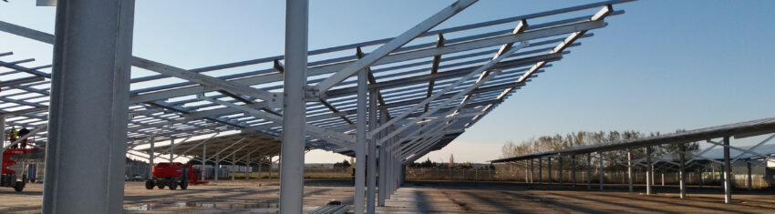
The different stages of a structural study for a photovoltaic shelter
In this page, we explain the different stages of a structural study. As an alternative, our software PV Shelters performs all these tasks for you.
Permanent loads
The permanent loads include the weight of the structure, the integration system, the solar panels, the wiring, and the equipment.
Suppliers of integration systems such as Adiwatt, Dome Solar, Heliosolaire , offer solutions adapted to roofs.
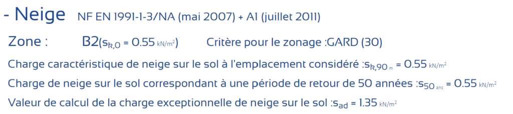
Snow action
The geographical location of the project is determined on the snow map of Eurocode 1, which allows to define the snow loads on the ground. This map provides the characteristic values of the snow load for different geographical regions depending on the altitude, latitude and longitude of the site.
The shape coefficient of the roof is then calculated. It takes into account the distribution of snow on the roof. The shape coefficient depends on the shape of the roof, the presence or absence of obstacles such as chimneys or dormers, and the exposure to wind. It is generally between 0.8 and 1.2. This coefficient is used to adjust the snow load calculated based on the geographical location of the project, as the shape and features of the roof can affect how snow accumulates and is distributed. By accounting for these factors, the shape coefficient helps ensure that the snow load is calculated accurately and that the roof is designed to withstand the specific snow loads it will encounter.
It is important to consider snow load in the design of the photovoltaic carport structure, as excessive snow load can cause deformation or even collapse of the structure.
Our software Eurocodes Zoning provides you with all the information about snow loads based on geographic location
Wind action
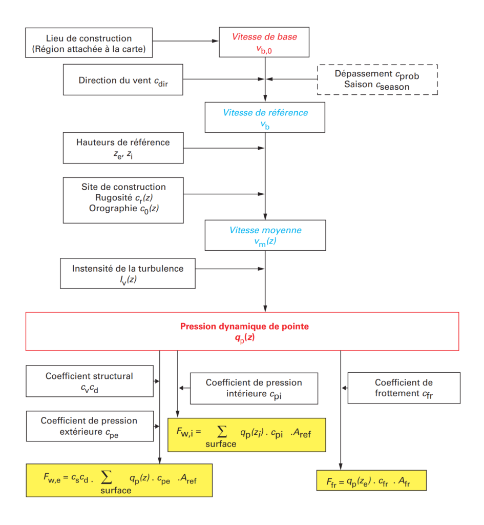
The geographical location of the project is determined on the wind map of Eurocode 1, which allows defining the characteristic values of the reference wind speed Vb,0 or the reference dynamic pressure qb,0.
It is also necessary to check for the presence of prevailing winds through the direction coefficient cdir. This coefficient is used to determine the basic dynamic pressure qb, which is then adjusted based on the terrain category and the orography coefficient.
The terrain category reflects the effect of the nearby environment of the construction (urbanization or vegetation) on the wind speed. Learn more about the roughness coefficient cr(z).
The orographic coefficient co(z) is related to the site’s relief and takes into account the effect of altitude and topography on wind speed. It is generally between 1 and 1.15.
Once these parameters are determined, it is possible to calculate the peak dynamic pressure qp,z, which will be used for the calculation of wind loads on the structure and the roofing.
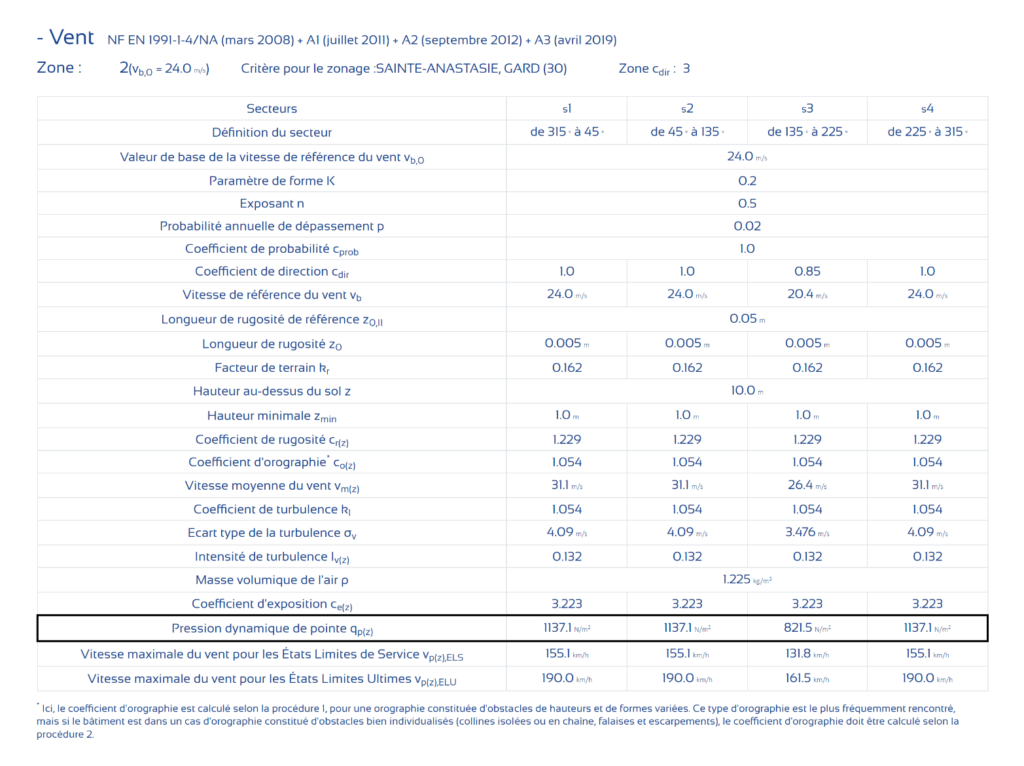
Our software Eurocodes Zoning provides detailed information on wind loads based on geographic location:
Wind actions on isolated roofs
Isolated roofs, such as photovoltaic shelters, have specific characteristics in terms of wind loading. The obstruction ratio, influenced by the presence of parked cars, is a determining factor in the calculation of overall force coefficients (Cf).
A high obstruction ratio leads to a greater uplift effect. Indeed, the airflow differs depending on whether the isolated roof is empty or there are parked cars underneath.
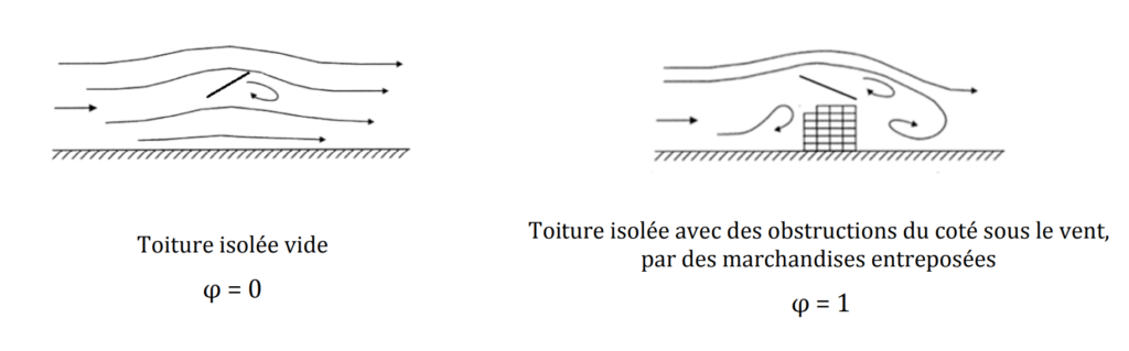
Table 2 of the “Recommendations for the application of NF EN 1991-1-4 to steel building frames and structures” provides all the necessary information for calculating wind loads on single-sloped isolated roofs.
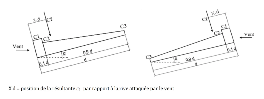
It is sometimes necessary to perform linear interpolations between the values in the table to estimate the pressure and force coefficients for intermediate angles or obstruction ratios.
Linear interpolation is represented by the equation:
\[\bar{f}(x)=\frac{y_a-y_b}{x_a-x_b} \cdot x+\frac{x_a \cdot y_b-x_b \cdot y_a}{x_a-x_b}\]When wind sweeps across large construction surfaces, significant frictional forces can develop tangentially to the surface. These forces act on surfaces parallel to the wind, depend on the surface roughness, and are determined using the friction coefficient. (Cfr).
Additionally, frictional forces also develop on metal profiles such as posts and rafters.
Seismic Zone
In France, photovoltaic shelters are generally not subject to seismic constraints due to the relatively low risk level and the legal texts that do not always require seismic design for structures that are not strictly buildings in the Eurocodes sense (equivalent to an importance category I). However, it is important to check local regulatory requirements and project specifications to determine if seismic design is necessary.

It is important to note that the seismic design of structures is governed by Eurocodes 8, which provide rules and calculation methods for determining seismic actions and designing structures.
Our software Eurocodes Zoning provides detailed information on seismic zones based on geographic location:
Structure analysis
Once all the loads are accounted for, they are applied to the structure via a modeling tool before initiating the analysis using a mechanical calculation solver. The modeling tool allows defining the geometry of the structure, material properties, and boundary conditions, while the solver performs the necessary calculations to determine deformations and forces within the structure.
The results of individual load cases (permanent loads, snow loads, wind loads) are combined together under various combinations defined in Eurocode 0. Load combinations may include partial safety factors to account for uncertainties related to loads and material resistances.
Design of structural elements
The design of the structural elements of the shelter, such as posts, beams, rafters, and braces, is carried out based on the previously calculated environmental loads and the characteristics of the chosen materials.
This design must comply with applicable safety and performance standards, especially the Eurocodes. Eurocodes are a series of European standards that provide common rules for the design of structures in concrete, steel, wood, etc. Eurocodes 3 and 5 are specifically used for the design of steel and wood structures, respectively.
This involves verifying that the elements are able to withstand each of the known modes of failure (shear, bending, buckling, overturning, warping, etc.). Verification of the strength of structural elements must be performed using calculation methods specified in the Eurocodes. The Eurocodes also provide characteristic strength values for different types of steel and wood, as well as methods for checking the stability and strength of structures subjected to various types of loads.
If the deformation and force values exceed the permissible limit values, it is necessary to reinforce the structure by adding structural elements, increasing section thickness, or using stronger materials.
Effect of temperature change
Temperature variations can lead to significant deformations in steel structures, which can affect their stability and strength. In the case of a shelter with a length greater than 50 m in bays of 10 m, it is necessary to include an expansion joint to allow the structure to expand and contract with temperature changes.
Expansion joints are devices that compensate for deformations due to temperature variations while maintaining the continuity of the structure. Sliding joints are generally recommended.
Wind beams must be placed on either side of this expansion joint to ensure the rigidity of the roof plane and the stability of the rafters (by limiting their lateral buckling length). These beams must be designed to withstand horizontal wind loads. The placement of these wind beams is free along the length of each section, but it is customary to place them in the middle of each section to limit the intensity of normal forces in the rafters.
Part 1-5 of Eurocode 1 provides calculation methods for the design of expansion joints in structures subjected to temperature variations.
Foundation verification
The foundations of the shelter are also calculated based on structural loads and site soil conditions. It is essential to ensure that the foundations are adequately sized to support the structure’s load and ensure its stability (primarily its balance and soil punching). To achieve this, it is important to consider soil characteristics such as bearing capacity, compressibility, and cohesion.
Foundations can be of various types, such as shallow foundations (footings), semi-deep foundations (piles), or deep foundations (piles, micropiles). The choice of foundation type depends on the soil type, the load to be supported, and the depth at which the foundations need to be anchored.
Foundation verification should be carried out in accordance with applicable standards, notably Eurocodes 7 for geotechnical calculation and Eurocode 2 for reinforced concrete calculation.
It is also recommended to conduct soil tests before foundation design to determine soil characteristics and verify project feasibility. These tests may include boring, penetration tests, and loading tests.
Best practice for creating metal frame plans
It is important to incorporate holes for galvanization drainage and to create an orientation hole in the rafters to indicate the high point of the rafter.
Drainage holes for galvanization help prevent the formation of air and moisture pockets inside the tubes, which can lead to premature corrosion of the structure. It is therefore recommended to provide drainage holes at the ends of the tubes and ensure that these holes are cleared after galvanization.
The orientation hole in the rafters is necessary to indicate the high point of the rafter and facilitate the assembly of the frame. It also ensures that the rafters are installed in the correct orientation.
It is also recommended to provide reinforcements (braces) and bracing to ensure the stability of the metal frame. Reinforcements can be placed where the structure is subjected to significant loads, while bracing is used to stiffen the structure and prevent deformations.
Finally, it is important to comply with applicable standards and regulations during the design and manufacture of the metal frame. Eurocodes 3 provide rules for the design and calculation of steel structures, while EN 1090 standards govern the manufacture and implementation of steel structures.